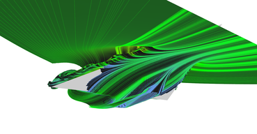
Realtime visualization of 3D vector fields using CUDA
Chapter 5: Visualization using stream surfaces
The last visualization technique is stream surfaces. The idea is very simple: seed stream lines on some curve (e.g. line) and triangulate space between each neighboring pair to create a surface. Advantage of stream surfaces is the fact that they can be shaded thus, easily see in 3D.
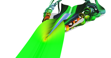
The problem is that some lines that started very close to each other diverge later in the vector field. The triangulation needs to stop if lines diverge, other wise visualization will be full of overlapping triangles. Figure 14 shows image sequence of stream surface seeded among line which is moving from front to back of the delta wing.
Triangulation of stream lines to form stream surface is done by pairs, every pair on separated CUDA thread. Triangulation of single pair of lines is implemented in following fashion. Going from the first vertices of the lines, there are always two ways how to add next triangle:
- Create triangle from indices
iandi + 1from the first line and indexjfrom second line, - or take index
ifrom the first and indicesjandj + 1from the second line.
The one which is "better" is picked and this continues till all points are triangulated or lines are too far away. Better triangle is determined as triangle with shorter edge between stream lines. Code listing 13 shows simplified CUDA kernel for creation of stream surface from stream line pairs (many implementation details omitted).
1
2
3
4
5
6
7
8
9
10
11
12
13
14
15
16
17
18
19
20
21
22
23
24
25
26
27
28
29
30
31
32
33
34
35
36
37
38
39
40
41
42
43
44
45
46
47
48
49
50
51
52
53
54
55
56
57
58
59
60
61
62
63
64
65
66
67
68
69
__global__ void computeStreamSurfaceKernel(uint2* linePairs,
		uint linePairsCount, float3* lineVertices,
		uint verticesPerLine, uint* lineLengths,
		uint3* outFaces, uint* outFacesCounts, float3* outNormals) {

	uint id = __umul24(blockIdx.x, blockDim.x) + threadIdx.x;
	if (id >= linePairsCount) {
		return;
	}

	uint2 currPair = linePairs[id];
	uint2 lengths = make_uint2(lineLengths[currPair.x], lineLengths[currPair.y]);

	if (lengths.x < 2 || lengths.y < 2) {
		outFacesCounts[id] = 0;
		return;  // Lines too short for triangulation.
	}

	uint line1Offset = currPair.x * verticesPerLine;
	uint line2Offset = currPair.y * verticesPerLine;
	float3* line1 = lineVertices + line1Offset;
	float3* line2 = lineVertices + line2Offset;
	float3* normals1 = outNormals + line1Offset;
	float3* normals2 = outNormals + line2Offset;

	uint maxFaces = verticesPerLine * 2 - 2;
	uint3* faces = outFaces + id * maxFaces;
	uint2 currIndex = make_uint2(0, 0);

	uint faceId;
	for (faceId = 0; faceId < maxFaces; ++faceId) {
		if (currIndex.x + 1 >= lengths.x || currIndex.y + 1 >= lengths.y) {
			break;  // Reached the end of stream line.
		}

		float dist1 = (currIndex.x + 1 < lengths.x)
			? length(line1[currIndex.x + 1] - line2[currIndex.y])
			: (1.0f / 0.0f);  // Infinity.
		float dist2 = (currIndex.y + 1 < lengths.y)
			? length(line1[currIndex.x] - line2[currIndex.y + 1])
			: (1.0f / 0.0f);  // Infinity.

		uint newVertexIndex;
		float3 newVertex;
		uint2 nextIndex;

		if (dist1 <= dist2) {
			newVertexIndex = line1Offset + currIndex.x + 1;
			newVertex = line1[currIndex.x + 1];
			nextIndex = make_uint2(currIndex.x + 1, currIndex.y);
		}
		else if (dist2 < dist1) {
			newVertexIndex = line2Offset + currIndex.y + 1;
			newVertex = line2[currIndex.y + 1];
			nextIndex = make_uint2(currIndex.x, currIndex.y + 1);
		}

		faces[faceId] = make_uint3(line1Offset + currIndex.x,
			line2Offset + currIndex.y, newVertexIndex);
		float3 normal = cross(line1[currIndex.x] - line2[currIndex.y],
			newVertex - line2[currIndex.y]);
		normal = normalize(normal);
		normals1[currIndex.x] = normal;
		normals2[currIndex.y] = normal;
		currIndex = nextIndex;
	}

	outFacesCounts[id] = faceId;
}
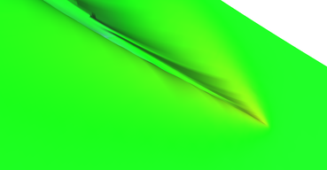
Stream surface (1) 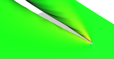
Stream surface (2) 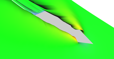
Stream surface (3) 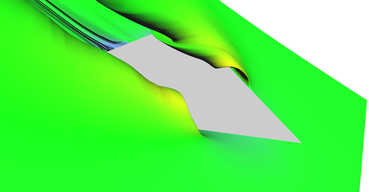
Stream surface (4) 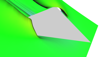
Stream surface (5) 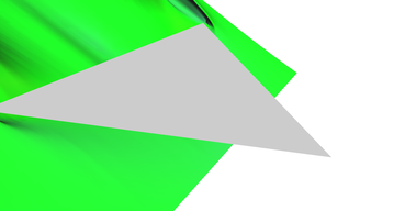
Stream surface (6)
Adaptive stream surfaces
The code for adaptive stream line seeding and code for stream surfaces generation have one important thing in common. Both algorithms work with line pairs. This means that they can be plugged together very easily (and that was intention from the beginning).
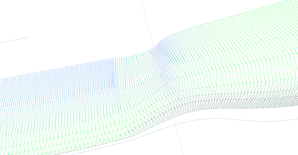
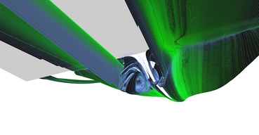
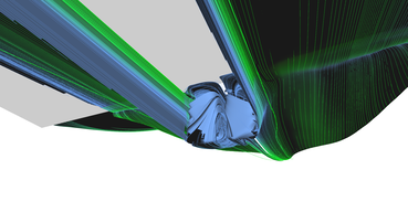
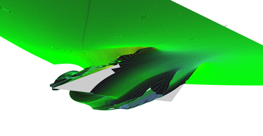
The only problem is that when line seeding is adaptive, criteria for breaking triangulation of lines which are too far away needs to be adaptive as well. Triangulation needs to work properly for lines which are close to each other as well as for lines starting further apart. The solution is that threshold for breaking is slowly adapting to the actual distance so if lines are diverging slowly, they will remain attached. This can be nicely observed at Figure 15 which shows wireframe of detail of stream surface.
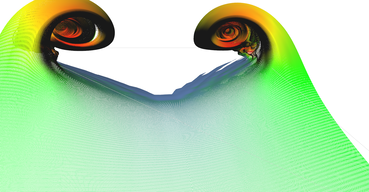
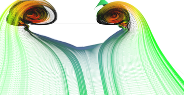
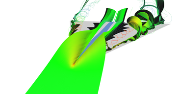
Figure 16 shows results of adaptive stream surface seeding. Some images have stream lines included in visualization too. Please note that I was not able to enable two-sided lightning model together with color material so one side of the surface is completely black.
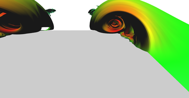
Adaptive stream surface (1) 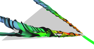
Adaptive stream surface (2) 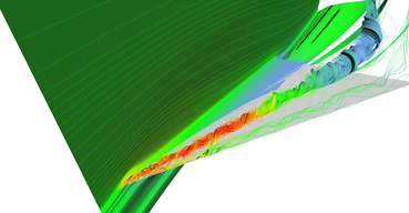
Adaptive stream surface (3) 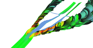
Adaptive stream surface (4) 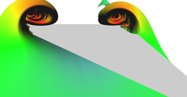
Adaptive stream surface (5) 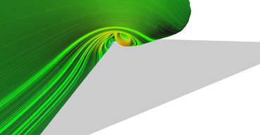
Adaptive stream surface (6)
Regular vs. adaptive seeding
Adaptive line seeding was implemented with hope that it will perform better than regular seeding with same number of lines. Figure 18 shows wireframe mesh of both methods for comparison. Side-by-side comparison is shown in Figure 17 and I think that adaptive seeding does better job than regular. However, nothing is for free, there is some performance drawback. Details about performance are in Chapter 6: Performance benchmark. Please note again that I was not able to enable two-sided lightning model together with color material so one side of the surface is completely black.
